Saturday, September 17, 2005

It's Finished (but in the end - I cheated)

As you may (or may not) recall, I set a target cost of max $200 for this project. Going into the framing stage, I was at $178. I had some frame material and mat board from an old (failed) print framing indeavor --- if I'd had a more steady and surer hand, I could have completed the project under the $200 limit, it may not have looked so great, but it would have worked. The frame really didnt' fit well, and the mat board was a really wierd color (even to me and I'm major color-blind). I wasn't happy with the framing and I couldn't cut the mat straight and I did want it to look decent.

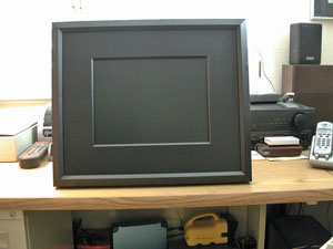
So, I cheated and solicited my friend Bryant Kelly of Prestige Gallery to help me out. I blew the budget, but I know I could have done it within the limits. I'm very happy with the result and have no regrets. At Bryant's suggestion, we used a matte black frame and mat board - which really makes the image stand out. We used small "easel" feet directly attached to the frame which allows it to stand on it's own.

Here are the results ---- pretty cool - huh?


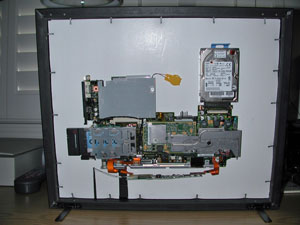
The back showing the system board side, and the Black on Black frame & Mat.

And, the finished project:

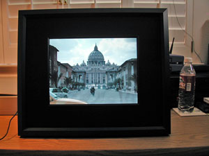
Is that way cool or what??


Monday, September 12, 2005

Mounted, and It Plays.......... Yes!!

Ok, the LCD Screen and the Systemboard are mounted to the mounting board using velcro.

It appears to be sturdy, and secure -- only time will tell. I really worked at getting the LCD screen square with the mounting board and once you let the sticky side of the velcro strips touch -- you're pretty much committed.

Then the acid test came -- applying power and seeing if it would play ........ and voila:

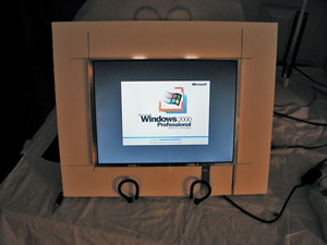
the mounting board is just set in a table-top easel for now.

Here it is with the slide show running.

Wireless networking is good-to-go, I can control it from my office pc, -- all that's left is getting the whole thing into a picture frame.

The next post should complete the project -- it's been a really fun one too.

Sunday, September 11, 2005

I Think I Figured Out How To Mount It

I decided that I would mount the laptop systemboard onto a piece of sturdy, but lightweight board and mount the LCD screen onto the opposide of that board .... then, mount the board into a picture frame.

In researching materials for the mounting board, I came across two products that I felt would serve the purpose well. One product is called Coroplast. It's a strong, but very lightweight corrugated plastic. It comes in sheets and in thicknesses of 4mm and up. I was having some trouble finding a single sheet of the right size and buying 10+ sheets would drive me over my overall project $ limit of $200.

My crafty wife Kay (the cute red-headed barmaid) suggested I look at Michels, a do-it-yourself crafts store. Sure enough, they had a 20"x30" sheet of Coroplast for $4.99. Just before I made the purchase decision, I noticed that they had 20"x30" sheets of foam board with placticized sides - also very sturdy and lightweight. The foamboard was about 3/16" thick and looked like it would work very well ...... and, it was $1.99 (just saved me $3.00)

The foamboard has proven to be very easy to work with and is easy to cut... etc with an X-Acto knife.

Below are come pictures to give you an idea what I'm talking about.

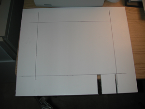
I cut the mounting board to 17" x 14" and squared an LCD screen sized rectangle in the middle - leaving a 2 3/4" border all around. The two slits at the bottom right are to allow the LCD cables to pass to the opposite side to connect to the system board

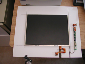
Here's the LCD Screen centered on the mounting board -- the cables will go through the slits to the opposite side to connect to the system board.

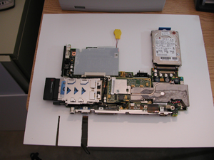
And here, the board has been flipped over, and the system board is roughly centered on it.

Placement of the systemboard onto the mounting board is not critical, as it will not be seen. Placement of the LCD screen is very critical as it must be perfectly square with the frame, otherwise, the image will be not be straight.

It is my intent to mount the LCD screen and the system board to the mounting board with velcro. I think velcro will work fine -- if not, then VHB (Very High Bond) tape will work. I prefer to use velcro as VHB tape is somewhat expensive, and isn't tolerent of mistakes.

So, the next step is to get these pieces actually mounted -- the cables connected and once again the power-on "does it play" test.

Thursday, September 08, 2005

More of a Challenge Than I Thought

Well, now that I'm all ready to mount the beast into a picture frame - it's proving more challenging than I thought. That means there will likely be further delays as I try different methods to see what works best.

My first action will be to mount the systemboard, hard drive ... etc onto some kind of backing board (plastic, or wood, or something). It needs to be rigid enough and strong enough to support the pieces without being bulky or heavy. My focus will be to try to use velcro wherever I can.

Then, I'll mount the LCD screen onto the opposide side of the board, where the cable can attach to the system board on the other side.

The bigger challenge will then to mount that assembly into a picture frame where the screen is perfectly square with the picture frame itself.

I'll report again when I make some positive progress.

Sunday, August 28, 2005

Dismantling of Laptop is Done!

Well, I've finished dismantling the laptop and have discarded(actually boxed in case I need something) all the pieces that I don't think I will need for the project.
Here's what's left of the laptop:
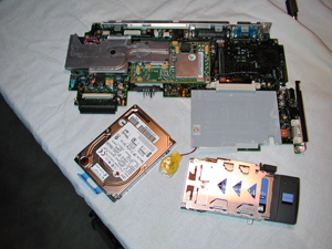
That's the hard drive on the lower left, the PCMCIA assemply on the lower right, and the System board with the RAM assembly attached at the top. the AC power socket and keyboard/mouse socket are indeed part of the systemboard assembly.

I struggled a bit getting the system board out of the plastic case. It just didn't want to come free, and I was afraid of forcing it and breaking something. I would work on it a while, set it aside, then go back and try again. After considerable amount of gentle prodding and coaxing, it finally came free and popped out intact.

The next step is to re-connect only these components, mate it with the LCD screen and (cross fingers) see if it plays ....................... And:

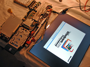
It's a beautiful thing.

The major project milestone has been reached successfully.

I'm having some difficulties getting the wireless network going again, but that's probably just a matter of playing and tinkering with it some.

There may be a lag in the project while I get that working, then try to figure out how to secure everything in a standard picture frame.

Friday, August 26, 2005

Moving On - The Final Dis-assembly

Well, here it is - what's left of a perfectly good, functioning Laptop computer:

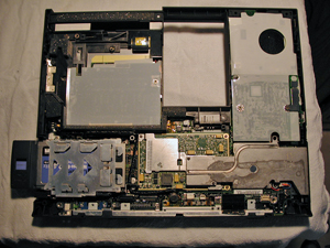
Within this conglomeration of stuff are some pieces and parts that are critical to the project. What I want to do here is remove those critical pieces and discard the rest. Not only do I want to remove the critical parts, but I need to do it in such a manner that I can re-assemble them in working order so that when I re-attach the LCD, it all boots up and plays and displays the slideshows as expected.

The critical pieces are: the system board, the PCMCIA (network) assembly, the hard drive assembly, and the RAM assembly. I also need a functioning On/Off switch, and the AC Power socket, and the Keyboard/Mouse socket. These may be part of the system board, but I won't know that for sure until I get further into the dis-assembly.

I'll try to get this done today, and will have a follow-up once I get it apart, and the critical pieces re-assembled and working to my satisfaction.

Fingers are crossed!

Friday, August 19, 2005

LCD Assembly Removed & Dismantled - Yeah

Before I start, I'm not sure if I mentioned previously that all the tech manuals for the Thinkpads are available in PDF format from Lenovo Support (They bought the PC division of IBM). These manuals describe the maintenance procedures including removal & parts replacement - in detail. They have been invaluable to me in this process.

I started on the LCD removal around 10AM and finished successfully at 1PM. It really didn't take that long (I had a bit of lunch.... etc), but I went very carefully and didn't want to force or break anything. Of course, my goal in this step is to plug it in to the system board after removal and dissassembly and have it boot up and work.

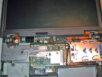
I've gotta get that top screen assembly off, then remove the LCD

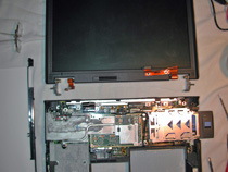
Well, they're separated - now to get the LCD out of the frame.

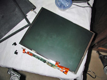
There it is in all it's nakedness - Hope it still works

and Voila: 
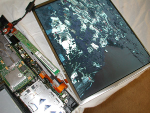
Slideshow is running and displaying fine ---- Yeah!.

This thing is rapidly ceasing to be a laptop computer.

Tomorrow or Sunday, I'll start removing the system board, RAM, PCMCIA, and HD assys -- then we'll re-connect all the wiring and see if the thing still plays.